Not bad for 90mW out of a Japanese radio made in 1971!
The small SWL beam (1...30 MHz)
Re: The small SWL beam (1...30 MHz)
Oh, nice! I wasn't aware that it is on an equatorial orbit but I derived from the slow Doppler effect that it wasn't very close. It went below the horizon a few minutes after shooting this:
Not bad for 90mW out of a Japanese radio made in 1971!
Not bad for 90mW out of a Japanese radio made in 1971!
-
Andrew (grayhat)

- Posts: 306
- Joined: Sat May 28, 2022 5:56 am
- Location: JN63pn
Re: The small SWL beam (1...30 MHz)
as for propagation, or lack of it
https://www.sciencealert.com/huge-canyo ... etic-storm
https://www.spaceweather.com/
https://www.sciencealert.com/huge-canyo ... etic-storm
https://www.spaceweather.com/
-
Andrew (grayhat)
- Posts: 306
- Joined: Sat May 28, 2022 5:56 am
- Location: JN63pn
Re: The small SWL beam (1...30 MHz)
a bit OT, but I was thinking at it and... ok, let me explain, let's say someone bought the "el cheapo" chinese MLA30 loop
https://www.g8jnj.net/activeantennas.htm#MLA30
now, if one has it in the junkbox, recovering it, replacing the noisy bias-t unit and adding it a BNC connector to use better coax will improve the poor thing a bit, but then...
let's say one replaces the loop with a diamond one, like the SDL we're discussing and then adds a 1K resistor to better match the preamp loop impedance (see the above link); the result may be interesting imHo
Re: The small SWL beam (1...30 MHz)
I don't have an MLA-30 but recycling its LNA might be worthwhile? No idea how good/bad it would be in a local-QRM-free environment? I have only 2 YouLoops I bought for crossloop/beam steering/QRM nulling experiments and all those plans are now becoming obsolete.
Last night the condx had recovered to a degree that 10m was good for some EU contacts and some more US signals returned. Alas the planned comparison with the amplified YouLoop didn't happen due to some location-related problems (illegal campers just on "my" spot at my listening post) so I moved to the alternate listening post a few km down the coast. There it turned out that some camping ground ~1km south of my position has installed some digital crap in the meantime, showing up faintly on the waterfall all over the SW. I was pretty annoyed but a little wrist-twist on the pole made that go away completely and that felt pretty good. I decided to just play with the SDL and gain more experience with it.
I was pretty puzzled that the 3V setting didn't yield the expected gain from the LANA HF tho, turned out this evening that the 2 examples I have are behaving differently - the second one I bought has ~6-10dB less gain than the other. Grrr. I was considering making a 2nd prototype to have an ideal reference for tweaks but this isn't fun if the LNAs don't do the same.
LANA HF #1 on 3V:
LANA HF #2 on 3V:
LANA HF #1 on 5V:
LANA HF #2 on 5V:
With the reduced gain MW looked even more bland than on the last attempt at the dike (with the better LNA) but browsing the band it dawned on me that what I was seeing on the waterfall was the yield of a beam turned NW, covering the remaining British stations more than anything else, and they were all there of course, including various local-ish private stations. Of course, it's still not that brilliant that it could bring in these stations during the day like my CCR2E would. Shortwave was not really something to phone home about but the IBP scans were plausible for the condix and brought the expected signals (Mt. Umum readable, KH6 not so much but WWVH was almost readble) in the morning, just as the LoG or vertical would have I guess.
Today I used a 50cm piece of rigid RG-402 I sourced to put the choke right behind the balun. I'm guessing that the number of ferrites is half of what's needed to be effective but the antenna is already not very balanced (edit: weight-balanced that is) anymore. Also to show why these plastic cable duct profiles are a good choice to make the support structure :
Here's the new LNA position:
Resistor pack detail:
Not sure/no idea if that choke made any difference but here's RAI Milano 900kHz when I rotate the antenna indoors (the pronounced null is exactly where it should be!):
Last night the condx had recovered to a degree that 10m was good for some EU contacts and some more US signals returned. Alas the planned comparison with the amplified YouLoop didn't happen due to some location-related problems (illegal campers just on "my" spot at my listening post) so I moved to the alternate listening post a few km down the coast. There it turned out that some camping ground ~1km south of my position has installed some digital crap in the meantime, showing up faintly on the waterfall all over the SW. I was pretty annoyed but a little wrist-twist on the pole made that go away completely and that felt pretty good. I decided to just play with the SDL and gain more experience with it.
I was pretty puzzled that the 3V setting didn't yield the expected gain from the LANA HF tho, turned out this evening that the 2 examples I have are behaving differently - the second one I bought has ~6-10dB less gain than the other. Grrr. I was considering making a 2nd prototype to have an ideal reference for tweaks but this isn't fun if the LNAs don't do the same.
LANA HF #1 on 3V:
- LNA1_3V.jpg (39.15 KiB) Viewed 46085 times
- LNA2_3V.jpg (38.26 KiB) Viewed 46085 times
- LNA1_5V.jpg (26.75 KiB) Viewed 46085 times
- LNA2_5V.jpg (27.1 KiB) Viewed 46085 times
Today I used a 50cm piece of rigid RG-402 I sourced to put the choke right behind the balun. I'm guessing that the number of ferrites is half of what's needed to be effective but the antenna is already not very balanced (edit: weight-balanced that is) anymore. Also to show why these plastic cable duct profiles are a good choice to make the support structure :
- SDL_Choke_sml.jpg (24.8 KiB) Viewed 46085 times
Here's the new LNA position:
- SDL_LNA_sml.jpg (59.64 KiB) Viewed 46085 times
Resistor pack detail:
- SDL_Resistor_sml.jpg (23.69 KiB) Viewed 46085 times
Not sure/no idea if that choke made any difference but here's RAI Milano 900kHz when I rotate the antenna indoors (the pronounced null is exactly where it should be!):
-
Andrew (grayhat)
- Posts: 306
- Joined: Sat May 28, 2022 5:56 am
- Location: JN63pn
Re: The small SWL beam (1...30 MHz)
Here's something which may be interesting
https://www.ve7ca.net/Ant160.htm#LNLoop
in this case there's no balun and the antenna uses a "special" preamp, but the notes about the choke may be of interest
as for the pattern, your tests show that the backside null is there and that it's deep enough, now, willing to make the upper angle of the front lobe narrower, will mean raising the resistor value (say to 1K or so), although that will also have two other effects, the impedance match to the 9:1 won't be so good as with a 530 Ohm resistor and the (negative) gain up to 30MHz will become lower, so I'm not sure such a mod may be convenient
regarding the MLA-30... no, not worth buying one, it was just an idea, since I have one of those, bought it time ago just for curiosity, but it's sitting unused down the basement, so I was thinking to resume it and run an experiment, but I doubt it will work as well as a real LNA
your note about being able to null out the QRM by just turning the antenna shows good promise for "apartment dwellers" it may mean that, installing the loop in a yard or balcony and aiming it "outside" it may be possible to cancel/attenuate the domestic noise and be able to pull in signals
that said, while the SDL doesn't seem to perform as in the (ideal) NEC model, I think it may still be worth some experimentation and may provably take more time to really assess what it can and can't do
forgot, 4NEC2 can open the exNEC model found at the above link, then saving it as ".nec" will allow to edit it if needed; ezNEC uses a "binary" format for model files. and that's one of the reasons why I prefer 4NEC2, since its textual model format allows to easily edit the models using whatever editor (I use notepad++) and also to easily insert symbols and calculated values
-
Andrew (grayhat)
- Posts: 306
- Joined: Sat May 28, 2022 5:56 am
- Location: JN63pn
Re: The small SWL beam (1...30 MHz)
Ok, had the time to run further NEC simulations, and the way the coax is routed does indeed influence the loop pattern, here's an example

as you can see, routing the coax along the horizontal arm and then down the vertical support or routing it "outside" the loop, makes quite a difference, in the first case, the cardioid pattern is "deformed" so, while there's still backside attenuation, it's lower, plus the upper angle of the beam is vertical, so making the loop sensitive to NVIS signals, changing the setup and routing the coax "outside" the loop, instead, shows a well formed cardioid pattern with a deep null and an upper vertical angle around 20° from vertical, so allowing to better attenuate NVIS signals
Now, I understand that routing the coax that way would be a mechanical challenge, but I think that using a run of thinner coax hanging from the feedpoint at the loop corner, down to a point of the vertical support below the loop bottom corner and then using fatter coax from there to the receiver may be a viable solution; also notice that routing the coax this way will minimize parasitic currents on the coax so, willing to add some chokes, we'd just need them on the "fatter" coax going down the vertical support
As a note, even if the above pic shows the simulation on 40m, I ran the model at different frequencies and ALL of them showed a consistent cardioid pattern with a deep backside null and a lower vertical angle, so I think that the somewhat strange receiving behavior you observed may have been due to the coax interfering (and modifying) the loop pattern
If you want to try running the simulation yourself, here's the model
as it is, the coax is routed "outside" the loop, willing to try the "inside" routing, just uncomment wires (GW tags) #10 and #11 and comment out #20, #21 and #22; what else... oh, yes, with that "outside" coax routing the loop remains directional even up at 90MHz and while the horizontal lobe is wider, the backside "null", even if not as marked as down on HF, is still there, so interference from FM stations will be attenuated and this, in turn, will help receivers with a poor front-end filter
Let me know if you'll need further infos or details
[edit]
forgot, look at the F/B figure of the loop when the coax is routed outside, the NEC simulation predicts 29.6dB of F/B ratio on 40m (38.2dB on 80m and 21.9 on 20m), which means that it could be possible to "cancel" even some blowtorch station just by turning the null toward it !
as you can see, routing the coax along the horizontal arm and then down the vertical support or routing it "outside" the loop, makes quite a difference, in the first case, the cardioid pattern is "deformed" so, while there's still backside attenuation, it's lower, plus the upper angle of the beam is vertical, so making the loop sensitive to NVIS signals, changing the setup and routing the coax "outside" the loop, instead, shows a well formed cardioid pattern with a deep null and an upper vertical angle around 20° from vertical, so allowing to better attenuate NVIS signals
Now, I understand that routing the coax that way would be a mechanical challenge, but I think that using a run of thinner coax hanging from the feedpoint at the loop corner, down to a point of the vertical support below the loop bottom corner and then using fatter coax from there to the receiver may be a viable solution; also notice that routing the coax this way will minimize parasitic currents on the coax so, willing to add some chokes, we'd just need them on the "fatter" coax going down the vertical support
As a note, even if the above pic shows the simulation on 40m, I ran the model at different frequencies and ALL of them showed a consistent cardioid pattern with a deep backside null and a lower vertical angle, so I think that the somewhat strange receiving behavior you observed may have been due to the coax interfering (and modifying) the loop pattern
If you want to try running the simulation yourself, here's the model
Code: Select all
CM File: DirLoop.nec
CM Small Receiving Loop antenna
CM with unidirectional pattern
CE

' symbols definition
SY freq=7.100               ' test frequenct
SY hght=3                   ' height of base corner from ground
SY side=0.762               ' length of one side
SY diag=(sqr(2)*(side/2))   ' half diagonal
SY wire=0.00125             ' wire radius
SY vres=530                 ' loading resistor value
SY segm=13                  ' number of segment in wires
SY segs=5                   ' short wires segments
SY wfed=1                   ' feedpoint wire
SY sfed=segm                ' feedpoint segment
SY wres=4                   ' wire hosting the resistor
SY sres=1                   ' segment hosting the resistor
SY spac=(wire*4)            ' spacing to simulate coax

' wires geometry
'  ID seg    x0     y0   z0         x1     y1     z1          wire rad
GW  1 segm     0     0  hght      -diag     0   hght+diag       wire
GW  2 segm     0     0  hght       diag     0   hght+diag       wire
GW  3 segm -diag     0  hght+diag     0     0   hght+(diag*2)   wire
GW  4 segm  diag     0  hght+diag     0     0   hght+(diag*2)   wire

' coax feeder
'GW 10 segs -diag  spac  hght+diag     0  spac   hght+diag       wire*2
'GW 11 segm     0  spac  hght+diag     0  spac      wire*4       wire*2
GW  20 segs -diag  spac  hght+diag -diag  spac   hght-diag       wire*2
GW  21 segs -diag  spac  hght-diag     0  spac   hght-diag       wire*2
GW  22 segs     0  spac  hght-diag     0  spac      wire*4       wire*2

' ground parameters
GE  1
GN  2  0  0  0  13  0.005

' wires loading
LD  5  0  0  0  58000000
LD  1 wres  sres sres vres 0

' enable extended kernel for calc
EK

' feedpoint
EX  0  wfed sfed 0 1 0 0

' initial test frequency
FR  0  1  0  0  freq  0

' end
EN
Let me know if you'll need further infos or details
[edit]
forgot, look at the F/B figure of the loop when the coax is routed outside, the NEC simulation predicts 29.6dB of F/B ratio on 40m (38.2dB on 80m and 21.9 on 20m), which means that it could be possible to "cancel" even some blowtorch station just by turning the null toward it !
-
Andrew (grayhat)
- Posts: 306
- Joined: Sat May 28, 2022 5:56 am
- Location: JN63pn
Re: The small SWL beam (1...30 MHz)
Oh, and before I forget, tried modeling the LoG in NEC and adding a resistor, but in that case the effect of the resistor is negative, since it only raises the takeoff angle, so such an approach isn't suitable for the LoG; if you're curious the simple LoG model I used is here
Code: Select all
CM ---------------------------------------------
CM File: LoG.nec
CM Loop on Ground - http://www.kk5jy.net/LoG/
CM antenna sideth changed using optimizer
CM feedpoint impedance set to 450 Ohms
CM ---------------------------------------------
CE

' symbols
SY freq=1.840             ' test frequency (MHz)
SY leng=18.288            ' loop perimeter (mt)   :: 21.336
SY side=(leng/4)          ' square loop side (mt) ::  4.572
SY wire=0.00075           ' antenna wire radius (mt)
SY hght=(wire*3.2)        ' height from ground (mt)
SY segs=25                ' total segments for each wire
SY fnum=1                 ' feedpoint wire #
SY fseg=1                 ' feedpoint wire segment #
SY vres=530               ' loading resistor value
SY wres=2                 ' loading resistor wire
SY sres=segs              ' loading resistor segment


' -------------------- antenna wires ---------------
'  #  segs  x0    y0   z0      x1    y1    z1    rad
'  -- ---- ----  ---- ----    ----  ----  ----  ----
GW  1 segs    0     0 hght    side     0  hght  wire
GW  2 segs side     0 hght    side  side  hght  wire
GW  3 segs side  side hght       0  side  hght  wire
GW  4 segs    0  side hght       0     0  hght  wire

' ground parameters
GE  -1
GN  2  0  0  0  13  0.005

' wires loading
LD 7  0  0  0  2.1  wire    ' insulator
LD 5  0  0  0 58000000      ' copper

' loading resistor
'LD 1 wres  sres sres vres 0

' antenna feedpoint params
EK
EX 0 fnum fseg 0 1 0 0

' test params
FR  0  1  0  0  freq  0

' end of model
EN
-
Andrew (grayhat)
- Posts: 306
- Joined: Sat May 28, 2022 5:56 am
- Location: JN63pn
Re: The small SWL beam (1...30 MHz)
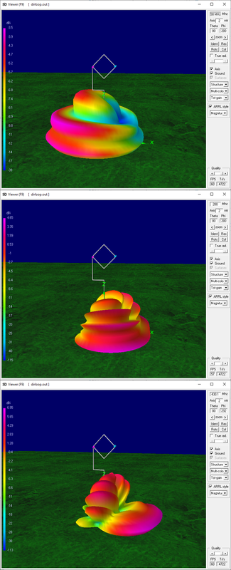
Further tests on the SDL show that, with the latest "coax routing" the directional pattern progressively changes, at around 120 MHz the antenna develops side lobes, while going up in frequency the beam is directed toward the resistor direction
Re: The small SWL beam (1...30 MHz)
Wow, that does seem to make a difference! BTW, that's how I initially intended to arrange the feedline, that's why I was asking "what horizontal stretch?" when we discussed this first.  But I wasn't fond of some coax permanently dangling around in the wind either, adding the pull of the coax to the weight and longer arm of balun and preamp, causing some really bad weight distribution causing the fiberglass pole tending to bow etc.
One easy way to address that would be finding the center of gravity of the entire antenna plus 1m of coax hanging off the balun/preamp, then screwing an additional vertical mounting support to the horizontal boom at that place. That will also shorten the length of coax required to reach the pole a bit and avoiding a lot of ferrite beads tied to one side of the boom would certainly help too.
After reading the interesting VE7CA article I tried to read up more on "W2DU"/"Maxwell" style current baluns and found interesting bits in this document:
https://citeseerx.ist.psu.edu/viewdoc/d ... 1&type=pdf
According to that, it's doesn't look that easy to create a CMC choke/current balun, there's more to it than clipping a high amount of random ferrite material beads onto some coax. I'd have yet to try the maximum available (like 12) clip-on ferrites tho, maybe that would work sufficiently well. However that the 6 beads I have on there now are not sufficient may explain why I had the impression that the beam seemed to flip around on some frequencies at home, and a bit hard to predict at the dike.
I wish I'd get more "dike time" and I didn't get to the dike on the weekend either, but I disassembled the antenna to double-check the integrity of the balun and the resistor (all OK) and to make some experiments indoors to check if the resistor value is having as much influence as the simulation suggests. Short answer: Yes! Changing the resistor to 760 Ohms (as a compromise between 530 and 1k Ohm) destroyed the sharp null on MW and playing with the simulation more I couldn't find any appreciable narrowing down of the horizontal or vertical beam with higher resistance?
The only thing that looks like a worthwhile variation (to me) is opening the loop circuit (R=infinity) to create a nice round and flat omnidirectional donut shaped pattern around the antenna, with much increased gain. This could be done by integrating a small SPDT into the support structure or small box, so the resistor can be switched in and out without much wiring hassle and disturbing the shape. A third switch position connecting the loop wire ends directly would change the omni pattern to a somewhat more oblong shape including the near-vertical incidence signals.
Oh well, time to get the antenna out of the trunk to change the feedline position. Looks like I didn't buy these 90° SMA bits in vain!
Edit: Playing with the new .nec file and comparing that to the old one it looks like this even has 3dB more gain on 17m and maybe more above (Edit again: 28.1 MHz loses a bit). The pattern really looks better and it retains more of a minimum (to avoid the term "null") on the upper bands (which I think is where this design is likely to shine most, also considering the upcoming solar maximum!).
-
Andrew (grayhat)
- Posts: 306
- Joined: Sat May 28, 2022 5:56 am
- Location: JN63pn
Re: The small SWL beam (1...30 MHz)
Guilty Your Honor !! The idea of routing the cable through the center of the loop was mine and mainly related to an attempt to avoid loading the support structure too much, but according to NEC that isn't a good idea <sigh>13dka wrote: ↑Mon Jul 25, 2022 3:34 pm Wow, that does seem to make a difference! BTW, that's how I initially intended to arrange the feedline, that's why I was asking "what horizontal stretch?" when we discussed this first.
another way may be using a short run of thinner coax describing a curve (in NEC i modeled that with corner just for simplicity) from the feedpoint down to the vertical support and from there start with "fat" coax; notice that judging from currents shown in NEC simulation, with such a routing the chokes may just be fitted on the "fat" coax running down the support and additional load shouldn't be a problem thereOne easy way to address that would be finding the center of gravity of the entire antenna plus 1m of coax hanging off the balun/preamp, then screwing an additional vertical mounting support to the horizontal boom at that place. That will also shorten the length of coax required to reach the pole a bit and avoiding a lot of ferrite beads tied to one side of the boom would certainly help too.
Maxwell chokes are easy, but the pitfall is that they're efficient only on a relatively narrow range of frequencies, a better approach would be winding a choke on a toroid core and possibly following the infos found here http://www.karinya.net/g3txq/chokes/ in such a case the choke may be hosted in a box hung on the vertical support at the point where the thin and the fat coax connect, but then, it also depends from IF we'll need chokes; if the preamp sits at the feedpoint, that alone should give decent isolation from CMCAfter reading the interesting VE7CA article I tried to read up more on "W2DU"/"Maxwell" style current baluns and found interesting bits in this document:
https://citeseerx.ist.psu.edu/viewdoc/d ... 1&type=pdf
According to that, it's doesn't look that easy to create a CMC choke/current balun, there's more to it than clipping a high amount of random ferrite material beads onto some coax. I'd have yet to try the maximum available (like 12) clip-on ferrites tho, maybe that would work sufficiently well. However that the 6 beads I have on there now are not sufficient may explain why I had the impression that the beam seemed to flip around on some frequencies at home, and a bit hard to predict at the dike.
removing the resistor from the circuit, the result will be an antenna with a pattern similar to KK5JY SRL http://www.kk5jy.net/rx-loop while opening the loop will result in a donut pattern similar to the one from a vertical antenna, the idea isn't bad at all and would give 3 antennas in one !The only thing that looks like a worthwhile variation (to me) is opening the loop circuit (R=infinity) to create a nice round and flat omnidirectional donut shaped pattern around the antenna, with much increased gain. This could be done by integrating a small SPDT into the support structure or small box, so the resistor can be switched in and out without much wiring hassle and disturbing the shape. A third switch position connecting the loop wire ends directly would change the omni pattern to a somewhat more oblong shape including the near-vertical incidence signals.
Well, sounds like we found a way to use those 90° adaptersOh well, time to get the antenna out of the trunk to change the feedline position. Looks like I didn't buy these 90° SMA bits in vain!
yes, gain seems to be a bit higher, and front-to-back much better, as for bands, it may be possible to optimize the antenna for lower frequencies by increasing the size and, probably, adjusting the height of the antenna from ground, just tried raising the side to 2m (ok, probably too much) and raising the antenna to 5m and obtained a "gain" of -48dB on the 160m band, while the 76cm side version has a "gain" of -64dB down there and -42dB on 40 meters, but before going for such a mod, I think exploring the performances with the modified feedline and doing that even down in frequency could be useful to decide "where to go next"; also, regarding gain, an alternative may be trying a higher gain preamp for the lower bands, there are some 30dB or more LNAs around, but then I'm not sure they may be worthEdit: Playing with the new .nec file and comparing that to the old one it looks like this even has 3dB more gain on 17m and maybe more above. The pattern really looks better and it retains more of a minimum (to avoid the term "null") on the upper bands (which I think is where this design is likely to shine most, also considering the upcoming solar maximum!).