Another directional RX loop
- Andrew (grayhat)
- Posts: 288
- Joined: Sat May 28, 2022 5:56 am
- Location: JN63pn
Another directional RX loop
this one is from QST
http://www.arrl.org/files/file/QEX_Next ... _10_12.pdf
the design is nice and the resulting antenna will probably offer good performance, but requires building phasing lines and them some, the advantage is that it is electronically "rotated" but then... compare it with the simplicity of the SULA antenna
Re: Another directional RX loop
For a fixed installation - looks like a worthwhile project! For portable usage and small spaces, well -> SULA!
- Andrew (grayhat)
- Posts: 288
- Joined: Sat May 28, 2022 5:56 am
- Location: JN63pn
Re: Another directional RX loop
Well, sure, that 4-loops isn't as easy to bring around as the SULA
Oh and if anyone is interested... I was curious to see if I could simplify that project while still having an "electronic steerable" directional antenna, so I started fiddling with NEC and the first thing I did was removing the phasing unit and using resistors on the 4 loops (yep, just like with the SULA) and after adjusting the various parameters, I got a nice result, the antenna takes a 6x6 square, and the apex of the 4 triangles is up 3.2m from ground, the match is good, the pattern is cardioid up to around 14MHz then it becomes omnidirectional (so not good at higher frequencies), gain ranges from -49dBi at 1MHz to -28dBi at 7MHz and -17dBi at 14MHz, adding a 20dB preamp will give an acceptable gain
Just for into, I'm posting a pic showing the antenna pattern and the swr and gain graphs; the triangles have the outer corner at 20cm from ground, the inner bottom corner at 50cm from ground and the upper corner at 3.20m from ground, the antennas are fed at the bottom inner corner and the resistor has a value of 775 Ohm and is placed 1/4 up from the bottom outer corner, the feedpoints are connected to a 9:1 BalUn (one for each loop) and then go to the relay box allowing to select the desired antenna, from there the coax goes to a choke and then to the station
Notice that, with respect to the other 4loop (the one with the phasing unit), this one has the pattern reversed, that is the lobe points toward the center pole and not toward the outside
( full size image here https://postimg.cc/2bJ4HMky )
- Andrew (grayhat)
- Posts: 288
- Joined: Sat May 28, 2022 5:56 am
- Location: JN63pn
Re: Another directional RX loop
and since we're at it... I "squeezed" the SULA
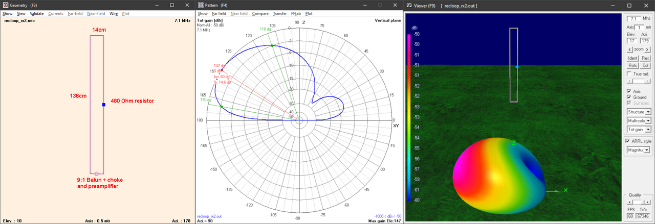
The idea was to find a more portable antenna, and after some fiddling I came out with this design
https://postimg.cc/56N9FqM4
the loop is made of 1.5mm insulated wire and the whole antenna could be built using a 140mm (OD) PVC pipe, by drilling four holes at the sides of the pipe it's possible to run the wire through the top holes and then run down on the external of the pipe to the bottom holes, the balun, choke and preamp may then sit inside the bottom part of the pipe (if desided the resistor may be placed inside the pipe as well) protected from rain, the top of the pipe is sealed with a cap and the same goes for the holes used to pass the loop wire
The antenna shows a cardioid pattern over the whole HF range and the pattern remains the same even if the antenna is installed at 1m from ground, gain is lower than the one offered by the SULA but still acceptable, at least on the HF bands, the advantage is that the antenna is very compact and easy to carry around; to install it one may use a piece of PVC pipe or fiberglass rod to hold the antenna to a metal pole, since we don't want any metal near the loop. The SWR curve is almost flat over the whole HF band (and beyond), the 9:1, preamp and choke may be the same used for the SULA
-
- Posts: 15
- Joined: Thu Jun 09, 2022 11:07 am
Re: Another directional RX loop
Thats a great idea!
Thanks for sharing. This version should be much easier to build for beginners than the SULA.
And a suitable balun and preamp can be found at very low cost on the web.
73
Egil - LA2PJ
Thanks for sharing. This version should be much easier to build for beginners than the SULA.
And a suitable balun and preamp can be found at very low cost on the web.
73
Egil - LA2PJ
- Andrew (grayhat)
- Posts: 288
- Joined: Sat May 28, 2022 5:56 am
- Location: JN63pn
Re: Another directional RX loop
Egil, notice that the BalUn is the same used with the SULA, and may either be bought (e.g. the NooElec 9:1 v2) or built (same as the one used here), the same goes for the choke, which may just be a string of 7 or more snap-on ferrites placed over the coax right after the preamp to form a so-called "Maxwell" or W2DU choke; as for the latter (the preamp), the nice thing is that, as for the SULA, this antenna offers an almost constant impedance match to 50 Ohm, so ANY preamp will fit, no need to use special designs used for loop antennas, ANY preamp will fit, although a gain from 15dB (or -better- more) is recommendedEgil - LA2PJ wrote: ↑Wed Mar 13, 2024 12:32 pm Thats a great idea!
Thanks for sharing. This version should be much easier to build for beginners than the SULA.
And a suitable balun and preamp can be found at very low cost on the web.
73
Egil - LA2PJ
- Andrew (grayhat)
- Posts: 288
- Joined: Sat May 28, 2022 5:56 am
- Location: JN63pn
Re: Another directional RX loop
Here's a general idea to build the antenna, notice that the resistor may be placed inside the upper pipe, by drilling two holes, also, the two pipes are both PVC ones, the top one is sealed at top with a cap and all holes used to pass through the wire are sealed with good sealant, the 9:1, preamp and choke are all hosted inside the bottom PVC pipe to keep them protected from rain and weather, the inner bottom of the lower pipe may be closed by a disc hosting a panel connector for the feeding coax
the wire loop has 2m total lenght, 140mm on the short sides, the remainder on the long sides; measures aren't critical, one may use 3 to 6 meters of wire and the antenna will still work
- Andrew (grayhat)
- Posts: 288
- Joined: Sat May 28, 2022 5:56 am
- Location: JN63pn
Re: Another directional RX loop
here's a better setup for the antenna; notice that the choke MUST be installed otherwise the cable could (would) become part of the antenna and totally screw the cardioid pattern; in this setup most of the wire runs inside the upper pipe so it's protected from UV and weather, same goes for the 9:1, preamp, choke and coax connector which are encased in the lower pipe
using two pipes for the antenna will also ease assembling the whole thing, and once the top cap, the wire holes, the junction and the bottom disc hosting the coax connector will be properly sealed the antenna will resist to weather w/o problems
Now, it remains to build and test it, if all goes well I'm planning to put together a raw model using a broomstick and some junkbox stuff and test if it works as the NEC simulation says, if so I may then go on and build it as for the above drawing
-
- Posts: 15
- Joined: Thu Jun 09, 2022 11:07 am
Re: Another directional RX loop
Andrew,
I decided to try your antenna idea, and made it pinned to the inside wall up in the loft, using your values for wires resistor and balun, and using a cheap RF amplifier I bought from Banggood:
https://www.banggood.com/Signal-Amplifi ... 12844.html
The antenna is mounted so the favoured directon is abour 240 degrees, which at my location is ideal for receiving signals from the north Atlantic Ocean and LatinAmerica.
The band conditions has been poor lately, but when monitoring Santa Maria Radio on 6628 kHz USB, with my Tecsun PL880 conected to the antenna late evening and night produced very good signals both from numerous flights and Santa Maria Radio. Also tried frequencies of south american broadcasters, but conditions was way too poor to hear them properly.
I have monitored the above frequency using the PL880 bedside the last year or so, using both the whip on the radio and a 14m long outside LW-antenna with very good results. But when connecting the radio to the new antenna, via 6 meters of RG178 coaxial cable, all signals became stronger and easier to hear, whith much less background noise than with the outside longwire.
The reduction of background noise really impressed me, so your antenna idea works great for me.
I have the free version of MMANA-GAL antenna simulation software installed on my laptop, so I put your values into the program and got the same oputput as you published,
This program is easier to use for amateurs than NEC, and can be downloaded from:
http://gal-ana.de/basicmm/download/download.php?mm=2
I also used the program to simulate the antenna with slightly larger values, 190 cm high and 30cm wide, and increasing the resstor to 680 ohms. That made the antenna even more directional with lower elevation angle on the main beam.
So I am going to change the meassures on the loft mounted antenna, and use the values given by MMANA GAL, when I get back home. If the antenna then works better than the one I use now, I will use it permanently and remove my outside antenna.
Here is the output from MMANA-GAL on 4, 12 and 15 MHz:
- Attachments
-
- 4MHz.png (53.5 KiB) Viewed 18477 times
-
- 12MHz.png (53.38 KiB) Viewed 18477 times
-
- 15MHz.png (53.47 KiB) Viewed 18477 times
- Andrew (grayhat)
- Posts: 288
- Joined: Sat May 28, 2022 5:56 am
- Location: JN63pn
Re: Another directional RX loop
Hi Egil !!
Happy to read that my impressions have been confirmed; while that antenna isn't "par up" with the SULA, its main advantage is the fact that it's really compact; as for the resistor value, yes, that one should be changed if the antenna size isn't the same as the one I posted, and then you may want to run a "sweep" using MMANA (I prefer NEC) to check the impedance match, see... the idea is to find a resistor value which gives acceptable match over the widest frequency range, that way the preamp (which is needed, since the antenna is small) will see a good match and offer good performance
If you can/want, it will be interesting to see a video comparing that antenna with the stock one (or with some other antenna)
Thank you again !
P.S. notice that the polarization of that antenna is vertical, yet as you found, it's UNIdirectional (cardioid pattern)