qrp-gaijin wrote: ↑Fri Oct 14, 2022 3:31 pm
I'm also curious if the SULA also exhibits a magnetic shadow region in the interior of the loop. I hope to run some simulations soon.
There seems to be a very small magnetic shadow effect visible in the SULA.
When illuminated from the front (non-null) side by a small vertical dipole located at x=-100, the magnetic near field inside the loop has a moderate field intensity, indicated by the light blue color.
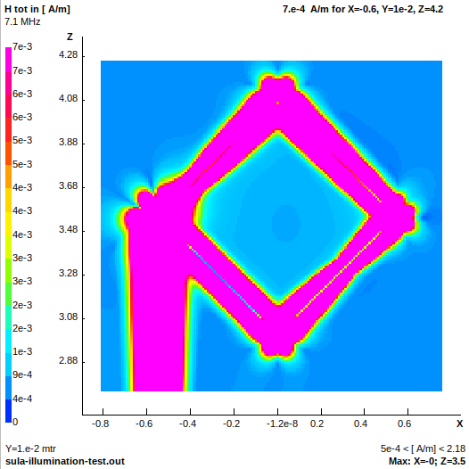
- sula-illumination-front.png (53.25 KiB) Viewed 22736 times
When illuminated from the rear (null) side by a small vertical dipole located at x=100, the magnetic near field inside the loop has a weaker field intensity, indicated by the darker blue color. This is the magnetic shadow effect.
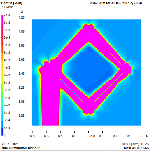
- sula-illumination-rear.png (53.74 KiB) Viewed 22736 times
Next question: what happens if we place an interior resonant loop inside the SULA, similar to the interior resonant loop of the CTL? Could we get a stronger shadow, and a stronger extracted signal thanks to resonance? I don't know. In this case, the untuned SULA loop -- with its pure resistive loading, but no inductive loading, and no resonating capacitor -- would need to serve the same role as the CTL's outer loop, but with a much reduced Q and much reduced current flow in the outer loop. Because the SULA is not resonant and is low Q, it's not clear to me if it will be able to serve the same role as the CTL's outer loop. I don't know if the non-resonant SULA loop will interact strongly enough with the interior resonant loop to provide good signal transfer and to enhance the magnetic shadow effect. For the original CTL design, Villard mentioned that the loading coils for the outer loop should be high-Q, implying that the entire outer loop should be high-Q, probably to preserve the Q of the interior loop, in order to extract the most signal from the resonant interior loop.
Many questions, not many answers... I'll try to put a resonant loop inside the SULA in 4nec2 and see what happens.
My intuition tells me that a non-resonant, low-Q outer loop (the SULA) cannot function as well as the tuned, high-Q outer loop in the CTL in producing the magnetic field shadow and in producing the unidirectional effect. I would think that there has to be some signal loss compared to the original CTL design. If the non-resonant SULA + resonant interior loop combination shows the same performance as the original CTL design, then this would mean that the CTL's outer resonant loop is needlessly complicated. Given the designer's credentials, I find that hard to believe, and suspect that Villard specifically used a high-Q, resonant outer loop because it was necessary for improved performance.
--
BEGIN EDIT
Updated information: I confirmed that a low-Q, non-resonant, resistively-loaded outer loop
does not work as a replacement for the high-Q, resonant outer loop of the CTL. To test this, I used my working CTL model, and removed the loading inductance and resonating capacitance from the outer loop, leaving only the load resistance in the outer loop, similar to the SULA. I placed the excitation source on the outer loop opposite of the load resistance (just as in the SULA NEC model) and optimized the resistance value for best F/B ratio. I could observe a cardioid pattern when the outer loop was excited, just as in the SULA. Then I relocated the excitation source onto the inner, resonant loop. No null appeared in the far-field data; the far field data instead appeared to be simply that of a normal small transmitting loop (a mostly symmetrical "blob"), and only a very small asymmetrical distortion of the far-field pattern occurred. In other words, the low-Q, non-resonant, resistively-loaded outer loop cannot cause the inner tuned loop to exhibit a cardioid pattern in the far field. I didn't bother with trying the near-field illumination test, because I'm pretty sure nothing would happen -- the non-resonant outer loop is simply not coupling very strongly to the resonant inner loop, and so has very small influence on the inner loop's near field and far field.
END EDIT
--
Here's the NEC file used to generate the above plots. I simply added a 0.1 meter long vertical dipole at x=-100 or x=100, moved the excitation source onto the dipole instead of the loop, and plotted the magnetic near field data around the loop.
Code: Select all
CM ----------------------------------
CM File: SULA.nec
CM ----------------------------------
CM
CM Small Unidirectional Loop antenna
CM
CM feed using a 9:1 balun transformer
CM keep the bottom corner at 3mt from
CM ground to avoid pattern distortion,
CM use a non conductive pole to raise
CM the antenna, optionally add a 20dB
CM or more preamp to raise the gain
CM
CM  symbols definition
CM SY wire=0.00635
CM  wires geometry
CM   ID seg    x0     y0   z0         x1     y1     z1          wire rad
CM  coax feeder "simulation" (may be changed to TL)
CM  ground parameters
CM  wires loading
CM  enable extended kernel for calc
CM  feedpoint
CM  initial test frequency
CM  end
CM
CM
CE
SY freq=7.100	'test frequency
SY hght=3	'height of bottom corner from ground
SY side=0.762	'length of one side
SY diag=(sqr(2)*(side/2))	'half diagonal
SY wire=0.00125	'wire radius
SY vres=530	'loading resistor value
SY segm=13	'number of segment in wires
SY segs=5	'short wires segments
SY wfed=1	'feedpoint wire
SY sfed=segm	'feedpoint segment
SY wres=4	'wire hosting the resistor
SY sres=1	'segment hosting the resistor
SY drop=hght-diag	'coax drop section length
SY coax=0.00250	'simulated coax radius
SY spac=(coax*3)	'spacing for coax routing
SY dist=diag+spac	'spacing for coax feedpoint
SY signal_antenna_x=-100
SY signal_antenna_len=0.1
GW	1	segm	0	0	hght	-diag	0	hght+diag	wire
GW	2	segm	0	0	hght	diag	0	hght+diag	wire
GW	3	segm	-diag	0	hght+diag	0	0	hght+(diag*2)	wire
GW	4	segm	diag	0	hght+diag	0	0	hght+(diag*2)	wire
GW	20	segs	-dist	0	hght+diag	-dist	0	drop	coax
GW	21	segs	-dist	0	drop	0	0	drop	coax
GW	22	segs	0	0	drop	0	0	spac	coax
GW	100	1	signal_antenna_x	0	hght+(side/sqr(2))-0.5*signal_antenna_len	signal_antenna_x	0	hght+(side/sqr(2))+0.5*signal_antenna_len	wire
GE	1
LD	7	0	0	0	2.1	wire	'insulation
LD	5	0	0	0	58000000	'copper wire
LD	1	wres	sres	sres	vres	0	'resistor
GN	2	0	0	0	13	0.005
EK
EX	0	100	1	0	1	0	0
FR	0	0	0	0	freq	0
EN

