Ok, had some time in my hand and decided to create a better model of the "cardioid loop" and run some simulation to check what to expect, after fiddling with various parameters and trying to optimize them, I came out with an antenna which presents an impedance of 450 Ohms, with low reactance, from 0.5 to 30 MHz (at least) so, with a 9:1 BalUn it will perfectly match whatever receiver, also, running the simulation, I found that the directionality characteristic of this antenna will remain almost unchanged on the whole range, this means that it won't just be directional up to about 10MHz but will keep a good F/B ratio even up to 30MHz; not bad, I think

- then ok, it remains to build and test it, but the model is very promising
The NEC model file is here (I used a script to generate it, instead of manually entering all the round loop segments)
Code: Select all
CM File: cardioid_loop.nec
CM Vertical cardioid loop antenna
CM impedance around 450 Ohm from 0.5 to 30 MHz
CM feed with a 9:1 BalUn
CE

' symbols
SY frq=7.100      ' test frequency
SY rad=0.5        ' loop radius
SY hgh=1.20          ' height from ground
SY ray=0.00125    ' wire radius
SY res=510        ' resistor
SY seg=3          ' segmentation

' loop geometry
GW   1 seg 0 rad*sin(0)   hgh+rad*cos(0)   0 rad*sin(10)  hgh+rad*cos(10)  ray
GW   2 seg 0 rad*sin(10)  hgh+rad*cos(10)  0 rad*sin(20)  hgh+rad*cos(20)  ray
GW   3 seg 0 rad*sin(20)  hgh+rad*cos(20)  0 rad*sin(30)  hgh+rad*cos(30)  ray
GW   4 seg 0 rad*sin(30)  hgh+rad*cos(30)  0 rad*sin(40)  hgh+rad*cos(40)  ray
GW   5 seg 0 rad*sin(40)  hgh+rad*cos(40)  0 rad*sin(50)  hgh+rad*cos(50)  ray
GW   6 seg 0 rad*sin(50)  hgh+rad*cos(50)  0 rad*sin(60)  hgh+rad*cos(60)  ray
GW   7 seg 0 rad*sin(60)  hgh+rad*cos(60)  0 rad*sin(70)  hgh+rad*cos(70)  ray
GW   8 seg 0 rad*sin(70)  hgh+rad*cos(70)  0 rad*sin(80)  hgh+rad*cos(80)  ray
GW   9 seg 0 rad*sin(80)  hgh+rad*cos(80)  0 rad*sin(90)  hgh+rad*cos(90)  ray
GW  10 seg 0 rad*sin(90)  hgh+rad*cos(90)  0 rad*sin(100) hgh+rad*cos(100) ray
GW  11 seg 0 rad*sin(100) hgh+rad*cos(100) 0 rad*sin(110) hgh+rad*cos(110) ray
GW  12 seg 0 rad*sin(110) hgh+rad*cos(110) 0 rad*sin(120) hgh+rad*cos(120) ray
GW  13 seg 0 rad*sin(120) hgh+rad*cos(120) 0 rad*sin(130) hgh+rad*cos(130) ray
GW  14 seg 0 rad*sin(130) hgh+rad*cos(130) 0 rad*sin(140) hgh+rad*cos(140) ray
GW  15 seg 0 rad*sin(140) hgh+rad*cos(140) 0 rad*sin(150) hgh+rad*cos(150) ray
GW  16 seg 0 rad*sin(150) hgh+rad*cos(150) 0 rad*sin(160) hgh+rad*cos(160) ray
GW  17 seg 0 rad*sin(160) hgh+rad*cos(160) 0 rad*sin(170) hgh+rad*cos(170) ray
GW  18 seg 0 rad*sin(170) hgh+rad*cos(170) 0 rad*sin(180) hgh+rad*cos(180) ray
GW  19 seg 0 rad*sin(180) hgh+rad*cos(180) 0 rad*sin(190) hgh+rad*cos(190) ray
GW  20 seg 0 rad*sin(190) hgh+rad*cos(190) 0 rad*sin(200) hgh+rad*cos(200) ray
GW  21 seg 0 rad*sin(200) hgh+rad*cos(200) 0 rad*sin(210) hgh+rad*cos(210) ray
GW  22 seg 0 rad*sin(210) hgh+rad*cos(210) 0 rad*sin(220) hgh+rad*cos(220) ray
GW  23 seg 0 rad*sin(220) hgh+rad*cos(220) 0 rad*sin(230) hgh+rad*cos(230) ray
GW  24 seg 0 rad*sin(230) hgh+rad*cos(230) 0 rad*sin(240) hgh+rad*cos(240) ray
GW  25 seg 0 rad*sin(240) hgh+rad*cos(240) 0 rad*sin(250) hgh+rad*cos(250) ray
GW  26 seg 0 rad*sin(250) hgh+rad*cos(250) 0 rad*sin(260) hgh+rad*cos(260) ray
GW  27 seg 0 rad*sin(260) hgh+rad*cos(260) 0 rad*sin(270) hgh+rad*cos(270) ray
GW  28 seg 0 rad*sin(270) hgh+rad*cos(270) 0 rad*sin(280) hgh+rad*cos(280) ray
GW  29 seg 0 rad*sin(280) hgh+rad*cos(280) 0 rad*sin(290) hgh+rad*cos(290) ray
GW  30 seg 0 rad*sin(290) hgh+rad*cos(290) 0 rad*sin(300) hgh+rad*cos(300) ray
GW  31 seg 0 rad*sin(300) hgh+rad*cos(300) 0 rad*sin(310) hgh+rad*cos(310) ray
GW  32 seg 0 rad*sin(310) hgh+rad*cos(310) 0 rad*sin(320) hgh+rad*cos(320) ray
GW  33 seg 0 rad*sin(320) hgh+rad*cos(320) 0 rad*sin(330) hgh+rad*cos(330) ray
GW  34 seg 0 rad*sin(330) hgh+rad*cos(330) 0 rad*sin(340) hgh+rad*cos(340) ray
GW  35 seg 0 rad*sin(340) hgh+rad*cos(340) 0 rad*sin(350) hgh+rad*cos(350) ray
GW  36 seg 0 rad*sin(350) hgh+rad*cos(350) 0 rad*sin(360) hgh+rad*cos(360) ray

' ground connection wire
GW  99 seg 0 rad*sin(170) hgh+rad*cos(170) 0 rad*sin(170)               0 ray

' end of geometry
GE  1

' ground parameters
GN  2  0  0  0  13  0.005

LD  7  0  0  0  2.1  ray        ' insulation
LD  5  0  0  0  58000000        ' copper
LD	0	 1	1	 1	res	0	0         ' resistor

' feeding
EK
EX 0 18  seg  0  1.0 0.0

' frequency
FR 0 1 0 0 frq 1

' end of model
EN
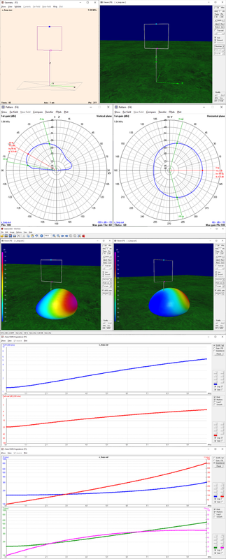
the antenna is a circular loop with 1m diameter placed at 1.20 m from ground (if placed higher the directional pattern will get lost when going up in frequency), the loop is broken at the top and the two halves are connected using a 510 Ohm resistor which allows to present a feedpoint impedance around 450 Ohm over the whole range, one of the halves of the loop is also connected to ground at the feedpoint, through a run of wire going straight down to a ground stake

- card_loop1.jpg (84.94 KiB) Viewed 7995 times
the wire, together with the top resistor, gives to this antenna its directional pattern

- card_loop2.jpg (184.1 KiB) Viewed 7995 times
as you can see, the pattern is somewhat less "marked" at 28 MHz, but it's still there and there's a good "null" at the back, so the resulting antenna should serve pretty well on the whole SW range, and then, thanks to the resistor and the optimization, the SWR curve at 450 Ohm (9:1 BalUn) is pretty good

- card_loop3.jpg (151.9 KiB) Viewed 7995 times
which means that, with a 9:1 BalUn, the antenna will match pretty well whatever "off the shelf" preamplifier or can be directly connected to any receiver w/o problems
[edit]
After some further simulations, I found that raising the loop to 1.20m from ground helps mantaining the F/B directional pattern on the whole SW range; also, thinking about the idea of modifying the MLA-30 into a "cardioid loop", I got back to the G8JNJ page describing the MLA-30
https://www.rtl-sdr.com/g8jnj-reverse-e ... p-antenna/
now, the preamp input circuit uses a pair of capacitor to connect the antenna, so connecting a ground wire to one of the preamp wing nuts (the ones used to connect the loop) won't cause problems to the circuit, also, Martin (G8JNJ) reports that the MLA-30 preamp input impedance is as follows
Code: Select all
1.5K Ohm at 1MHz
1.4K Ohm at 10MHz
600 Ohm at 20MHz
450 Ohm at 30MHz
now, since we can control the loop impedance by changing the resistor value, we may select a resistor with a value of about 1KOhm so that the resulting loop will present a better match to the preamp input; I've just ran a simulation setting the resistor to 1.5K and the loop, with such a resistor presents an impedance of 1.4K at 1.8MHz and 293Ohm at 28MHz, while not perfect, it would be a pretty decent match to the MLA preamp