Page 1 of 1
Matching transformer for random wire?
Posted: Sun Apr 16, 2023 5:55 pm
by mckayprod
I'm having good luck with my End-fedz SWL antenna but I want to experiment with a longer-wire version of that general approach. I have an old Radio Shack random wire SWL antenna and I want to feed the receivers with coax, so some kind of unun transformer seems correct. Is there a proper ratio that is known to work? I see 9:1, 4:1, even 49:1 units on ebay, and without buying one of each and trying them out or getting into modeling software, I don't know where to start. Any antenna experimenters on the forum with some advice?
Re: Matching transformer for random wire?
Posted: Mon Apr 17, 2023 8:41 am
by Egil - LA2PJ
Some years ago I had exactly the same problem as you. A friend adviced me to build a simple antenna tuner, and a quick search on the internet resulted in a link to a building instruction for an antenna tuner in PDF format by someone calling himself Editor Bob.
Since then I have built two more of these tuners, since the result was very satisfactory.
I was not able to attach the PDF, seems like the forum accepts bitmaps only as attachments. So attach a screendump of the scematic. If I only knew your email adress, I would be happy to send you the PDF.
Goood luck!
Egil - LA2PJ
- ATU.gif (33.03 KiB) Viewed 6201 times
Re: Matching transformer for random wire?
Posted: Wed Apr 19, 2023 3:31 pm
by Andrew (grayhat)
mckayprod wrote: ↑Sun Apr 16, 2023 5:55 pm
I'm having good luck with my End-fedz SWL antenna but I want to experiment with a longer-wire version of that general approach. I have an old Radio Shack random wire SWL antenna and I want to feed the receivers with coax, so some kind of unun transformer seems correct. Is there a proper ratio that is known to work? I see 9:1, 4:1, even 49:1 units on ebay, and without buying one of each and trying them out or getting into modeling software, I don't know where to start. Any antenna experimenters on the forum with some advice?
the "problem" with a random wire is that it can't be so "random" that is, there are some lenghts to avoid if you want to use a transformer to match them to a coax, the whole thing is explained in detail here
https://udel.edu/~mm/ham/randomWire/
along with a chart showing the lenghts which allow to obtain a good match using a 9:1 transformer, then, in addition to the transformer. you may consider the idea of building (or buying) an antenna matching unit, the latter, for RX use only, should be pretty cheap, since it won't need to support any TX power
As a last note, all endfed antennas will require a counterpoise wire and a good choke placed after the transformer, they will work without it, sure, but in such a case, your coax braid will become part of the antenna, and will pick up noise from any noise source it will pass nearby, not a good thing
Re: Matching transformer for random wire?
Posted: Wed Apr 19, 2023 3:43 pm
by Andrew (grayhat)
A good size for a random is an 84ft antenna wire and a 17ft counterpoise wire, to connect them to the coax you may use this 9:1
https://www.nooelec.com/store/balun-one ... bones.html
enclosed in a small weatherproof box, add an adapter to connect the SMA to whatever coax connector you use (I prefer BNC) and add at least 6 (12 would be even better) snap on ferrites to the coax immediately after the balun to choke off common mode currents, suspend the antenna as high and clear as possible (the counterpoise may just dangle down) and you'll be in business

Re: Matching transformer for random wire?
Posted: Fri Apr 21, 2023 2:58 am
by mckayprod
Thanks for all the ideas. I thought that since this antenna was so common (Radio Shack has surely sold thousands, not to mention the Philmore branded versions) there might be a quick, well-known choice. I may try the tuner design in Andrew's first reply. Funny how well the End-fedz works without a counterpoise, though the coax is grounded at both ends with 8' copper-plated rods. Thanks again!
Re: Matching transformer for random wire?
Posted: Fri Apr 21, 2023 8:30 am
by Andrew (grayhat)
willing to avoid an ATU and to have a better S/N ratio, you may consider putting up a different type of antenna, I'm referring to the T2FD

it's basically a folded dipole with a termination resistor, it can be easily built using stranded, insulated wire and some wooden or plastic spacers, the resistor value will be around 600 Ohm and the balun will be a 9:1, followed by a choke, such an antenna will offer a pretty good match to the 50 Ohm coax over a very wide range of frequency and the load resistor will also shunt a lot of noise so offering better reception
For RX only a precise size isn't so important, willing to use the antenna for TX too, the size (in meters) is calculated as follows
total span = 100/MHz
spacing = 3/MHz
where MHz is the lowest operating frequency, also, for TX the resistors should be able to sustain up to the 70% of the max TX power, while for RX only this isn't a problem
willing to buy parts, you may check here
https://palomar-engineers.com/rfi-kits/ ... d-dipoles/
but for an RX only setup, you may just use the nooelec 9:1 and some "standard" cheap resistors
Re: Matching transformer for random wire?
Posted: Fri Apr 21, 2023 10:29 am
by Andrew (grayhat)
forgot, if you want to build your own impedance transformer, it's easy, just follow the directions here
http://www.aytechnologies.com/TechData/9-to-1_XFMR.htm
as for the core, 77, 73 and 43 materials will be ok, one turn is counted each time the two ends of the wire enter the binocular holes and exit to the opposite side, again that's ONE turn, not a half one

The transormation ratio (and windings count) is easy to calculate, just a matter of calculating a square root, let's say we want a 9:1 transormation ratio, we calculate the square root of 9 obtaining 3, so the winding ratio will be 3, this means that, winding 9 turns and then 3 turns (9:3) we'll have a 9:1 impedance transformer
Adapting that to other ratios is, as you can see, really easy

Re: Matching transformer for random wire?
Posted: Fri Apr 21, 2023 12:01 pm
by Andrew (grayhat)
Oh and as for the ATU check out this one
https://pa0fri.home.xs4all.nl/ATU/FRIma ... tcheng.htm
for RX only (or for QRP use) it can be built using a pair of polyvaricons
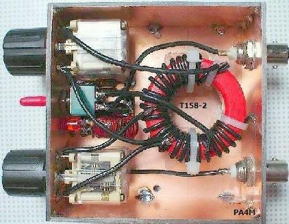
also, while the original design covers the range between 3 and 30 MHz, willing to go lower in frequency isn't difficult. just a matter of increasing the inductance, sure, in such a case we'll loss a portion of the higher frequencies, but then maybe it won't be a problem