Here's an interesting antenna design from "Cross Country Wireless"
http://www.crosscountrywireless.net/car ... ntenna.htm
while I didn't (yet) build/test it, the idea is quite interesting and it's basically the same which was used in a past for radiogoniometers, in that case they used a loop and a whip, in this case the whole thing is composed just by a "modified" loop, in short, if you check the above page, the loop has a resistor at the top, splitting it in two, at that point, one half of the loop becomes a reflector and the "8" shaped radiation pattern of the loop changes to a directional cardioid shape, the resulting antenna, according to the author, will mantain its directional cardioid pattern up to 8MHz so it will be a great resource for low bands and, by the way, MW and LW bands
The original design (above) claims for a CCW loop antenna preamplifier, but I wonder if it may be possible to use a balun and then connect the loop to whatever preamplifier, again, didn't go on and build it (yet) and hope to find some time in a future, then if someone here wants to experiment with such an antenna, I'll be surely interested in hearing about the results
[edit]
a short discussion about the above cardioid loop can be found here
https://groups.io/g/CrossCountryWireles ... 8194527?p=
The cardioid loop
-
Andrew (grayhat)

- Posts: 305
- Joined: Sat May 28, 2022 5:56 am
- Location: JN63pn
Re: The cardioid loop
Ok, being curious decided to download the NEC model file from the CCW page and ran it, found that the impedance of the antenna in the range between 1KHz and 10MHz varies between 600Ohm and 1KOhm, so I ran a sweep setting the feeder impedance to 800Ohm that is feeding the antenna through a 16:1 BalUn, the result is the graph below (full image: download/file.php?id=16)
which shows a pretty good curve, this means that winding a BalUn with a 16:1 transformation ratio (4:1 turns ratio) will allow to use whatever preamp which accepts a 50Ohm input  ! Also, the NEC simulation confirmed the cardioid pattern, so the antenna may really be worth a try, also since a beam antenna for those low frequencies isn't exactly a "little thing"
Notice that the BalUn may be built following the same design used for the NCPL antenna but changing the primary/secondary turns to obtain a 4:1 turns ratio, for example 8 turns toward the antenna and 2 turns toward the coax, the resulting balun will have an impedance transformation ratio of 16:1
Note: the NEC model on the page is for the LARGER version of the loop (optimized from 1.8MHz and down), the smaller one presents a feedpoint impedance between 100 and 200 Ohms so a 2:1 or 4:1 BalUn will fit in such a case
- card_loop_swr.png (54.17 KiB) Viewed 25694 times
Notice that the BalUn may be built following the same design used for the NCPL antenna but changing the primary/secondary turns to obtain a 4:1 turns ratio, for example 8 turns toward the antenna and 2 turns toward the coax, the resulting balun will have an impedance transformation ratio of 16:1
Note: the NEC model on the page is for the LARGER version of the loop (optimized from 1.8MHz and down), the smaller one presents a feedpoint impedance between 100 and 200 Ohms so a 2:1 or 4:1 BalUn will fit in such a case
Re: The cardioid loop
That's a pretty interesting design, thanks for the heads up! I wonder if and how this principle could be applied to big loops (because I find SMLs tend to lack a lot above 10 MHz)?
-
Andrew (grayhat)
- Posts: 305
- Joined: Sat May 28, 2022 5:56 am
- Location: JN63pn
Re: The cardioid loop
well, the NEC model (which I used for tests) was related to the bigger loop, optimized for 160m and down, and that vertical loop is a square with 4m sides so not so small, then while fiddling with NEC I found that the resistor value should be changed depending from the overall loop size to obtain the desired directional pattern, but... yes, the idea will work for larger loop
-
Andrew (grayhat)
- Posts: 305
- Joined: Sat May 28, 2022 5:56 am
- Location: JN63pn
Re: The cardioid loop
Ok, got a bit of time and "massaged" the original NEC model a bit, the resulting model is here
as you can see I changed the loop size to be a square with a 1m side, placed at 1.5m above ground and with a 160Ohm resistor, the resulting loop has an impedance around 200 Ohm and can be fed using a 4:1 BalUn, the cardioid pattern is the same so the antenna retains the directional characteristics, given the pretty low gain, a preamp may be needed, although it may be interesting to experiment without it
here are some graphs from the NEC simulation (click on the image for full size)
which show the antenna structure, pattern and the impedance/SWR graphs, the reactance of the antenna could be lowered by raising the resistor value to around 330Ohm but then the pattern will loose some directionality, so I'm not sure it may be a good idea
Code: Select all
CM Cardioid loop design by Chris Moulding G4HYG based on original C & S
CM loop array design from 1982.
CM Loop size (side), height and resistor value can be adjusted in the Editor.
CM This version has corrected orientation to allow the Optimiser to be used
CM to calculate the optimum resistor value for best F/B ratio.
CE

SY freq=1.84
SY height=1.5       '' 1
SY wire=0.0002
SY rres=160         '' 645.3372
SY side=0.5         '' 2
SY lseg=5
SY sseg=1
SY rseg=lseg/2

GW  1  lseg   side  0  height+2side  -side  0  height+2side  wire
GW  2  lseg   side  0  height+2side   side  0  height        wire
GW  3  lseg  -side  0  height+2side  -side  0  height        wire
GW  4  lseg   side  0  height            0  0  height        wire
GW  5  sseg     0   0  height            0  0       0        wire
GW  6  lseg  -side  0  height            0  0  height        wire

GE  1
GN  2  0  0  0  13  0.005

LD  0  1  rseg  rseg  rres  0  0


EK
EX  0  4  lseg  0  0  0  0

FR  0  0  0  0  freq  0

EN
here are some graphs from the NEC simulation (click on the image for full size)
which show the antenna structure, pattern and the impedance/SWR graphs, the reactance of the antenna could be lowered by raising the resistor value to around 330Ohm but then the pattern will loose some directionality, so I'm not sure it may be a good idea
Re: The cardioid loop
Thanks for that! This is absolutely something I want to play with, it's easy enough. Couldn't you have posted that before I bought this expensive phasing unit to make experiments with the original ADF antenna principle (loop + sense antenna) at the dike?
-
Andrew (grayhat)
- Posts: 305
- Joined: Sat May 28, 2022 5:56 am
- Location: JN63pn
Re: The cardioid loop
I'm sorry !! Truth is ... that I found that antenna quite some time ago, but I stumbled upon it again just lately and thought it could be of interest to the people here; at any rate, the phasing unit may still be useful, those "cardioid loops" may be combined, using a phaser, to obtain a narrower lobe, have a look at page #6 in this PDF document http://www.bscassociates.co.uk/Bibliogr ... per-06.pdf
Re: The cardioid loop
Thanks! Yes, the more the merrier, the sense/loop arrangement came into my mind first because that's what I have in my trunk all the time (vertical fiberglass pole and some loops) but I'm also curious on (small) arrays in general, particularly a LoG array. So much to play with, so little time! 
-
Andrew (grayhat)
- Posts: 305
- Joined: Sat May 28, 2022 5:56 am
- Location: JN63pn
Re: The cardioid loop
Just had an idea; what about transforming one of those "chinese loop antennas" like the MLA-30, into a cardioid loop ? Mine is down the basement, so it will take some time to put it back on duty, but if someone here had an MLA at hand, I think it may be an interesting experiment; it would require replacing the original loop with a 1m diameter one, cut at the top and connected to the resistor, at that point when connecting the loop to the MLA preamp box, we'll need to connect to one of the screws a run of insulated wire which will go to a ground stake so obtaining the "cardioid" configuration; again, didn't try it, but may be worth an experiment since may turn the MLA into a far better antenna
-
Andrew (grayhat)
- Posts: 305
- Joined: Sat May 28, 2022 5:56 am
- Location: JN63pn
Re: The cardioid loop
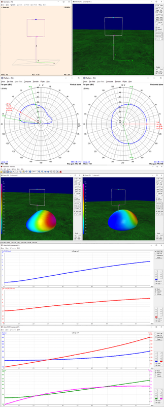
Ok, had some time in my hand and decided to create a better model of the "cardioid loop" and run some simulation to check what to expect, after fiddling with various parameters and trying to optimize them, I came out with an antenna which presents an impedance of 450 Ohms, with low reactance, from 0.5 to 30 MHz (at least) so, with a 9:1 BalUn it will perfectly match whatever receiver, also, running the simulation, I found that the directionality characteristic of this antenna will remain almost unchanged on the whole range, this means that it won't just be directional up to about 10MHz but will keep a good F/B ratio even up to 30MHz; not bad, I think - then ok, it remains to build and test it, but the model is very promising
The NEC model file is here (I used a script to generate it, instead of manually entering all the round loop segments)
the antenna is a circular loop with 1m diameter placed at 1.20 m from ground (if placed higher the directional pattern will get lost when going up in frequency), the loop is broken at the top and the two halves are connected using a 510 Ohm resistor which allows to present a feedpoint impedance around 450 Ohm over the whole range, one of the halves of the loop is also connected to ground at the feedpoint, through a run of wire going straight down to a ground stake
the wire, together with the top resistor, gives to this antenna its directional pattern
as you can see, the pattern is somewhat less "marked" at 28 MHz, but it's still there and there's a good "null" at the back, so the resulting antenna should serve pretty well on the whole SW range, and then, thanks to the resistor and the optimization, the SWR curve at 450 Ohm (9:1 BalUn) is pretty good
which means that, with a 9:1 BalUn, the antenna will match pretty well whatever "off the shelf" preamplifier or can be directly connected to any receiver w/o problems
[edit]
After some further simulations, I found that raising the loop to 1.20m from ground helps mantaining the F/B directional pattern on the whole SW range; also, thinking about the idea of modifying the MLA-30 into a "cardioid loop", I got back to the G8JNJ page describing the MLA-30
https://www.rtl-sdr.com/g8jnj-reverse-e ... p-antenna/
now, the preamp input circuit uses a pair of capacitor to connect the antenna, so connecting a ground wire to one of the preamp wing nuts (the ones used to connect the loop) won't cause problems to the circuit, also, Martin (G8JNJ) reports that the MLA-30 preamp input impedance is as follows
now, since we can control the loop impedance by changing the resistor value, we may select a resistor with a value of about 1KOhm so that the resulting loop will present a better match to the preamp input; I've just ran a simulation setting the resistor to 1.5K and the loop, with such a resistor presents an impedance of 1.4K at 1.8MHz and 293Ohm at 28MHz, while not perfect, it would be a pretty decent match to the MLA preamp
The NEC model file is here (I used a script to generate it, instead of manually entering all the round loop segments)
Code: Select all
CM File: cardioid_loop.nec
CM Vertical cardioid loop antenna
CM impedance around 450 Ohm from 0.5 to 30 MHz
CM feed with a 9:1 BalUn
CE

' symbols
SY frq=7.100      ' test frequency
SY rad=0.5        ' loop radius
SY hgh=1.20          ' height from ground
SY ray=0.00125    ' wire radius
SY res=510        ' resistor
SY seg=3          ' segmentation

' loop geometry
GW   1 seg 0 rad*sin(0)   hgh+rad*cos(0)   0 rad*sin(10)  hgh+rad*cos(10)  ray
GW   2 seg 0 rad*sin(10)  hgh+rad*cos(10)  0 rad*sin(20)  hgh+rad*cos(20)  ray
GW   3 seg 0 rad*sin(20)  hgh+rad*cos(20)  0 rad*sin(30)  hgh+rad*cos(30)  ray
GW   4 seg 0 rad*sin(30)  hgh+rad*cos(30)  0 rad*sin(40)  hgh+rad*cos(40)  ray
GW   5 seg 0 rad*sin(40)  hgh+rad*cos(40)  0 rad*sin(50)  hgh+rad*cos(50)  ray
GW   6 seg 0 rad*sin(50)  hgh+rad*cos(50)  0 rad*sin(60)  hgh+rad*cos(60)  ray
GW   7 seg 0 rad*sin(60)  hgh+rad*cos(60)  0 rad*sin(70)  hgh+rad*cos(70)  ray
GW   8 seg 0 rad*sin(70)  hgh+rad*cos(70)  0 rad*sin(80)  hgh+rad*cos(80)  ray
GW   9 seg 0 rad*sin(80)  hgh+rad*cos(80)  0 rad*sin(90)  hgh+rad*cos(90)  ray
GW  10 seg 0 rad*sin(90)  hgh+rad*cos(90)  0 rad*sin(100) hgh+rad*cos(100) ray
GW  11 seg 0 rad*sin(100) hgh+rad*cos(100) 0 rad*sin(110) hgh+rad*cos(110) ray
GW  12 seg 0 rad*sin(110) hgh+rad*cos(110) 0 rad*sin(120) hgh+rad*cos(120) ray
GW  13 seg 0 rad*sin(120) hgh+rad*cos(120) 0 rad*sin(130) hgh+rad*cos(130) ray
GW  14 seg 0 rad*sin(130) hgh+rad*cos(130) 0 rad*sin(140) hgh+rad*cos(140) ray
GW  15 seg 0 rad*sin(140) hgh+rad*cos(140) 0 rad*sin(150) hgh+rad*cos(150) ray
GW  16 seg 0 rad*sin(150) hgh+rad*cos(150) 0 rad*sin(160) hgh+rad*cos(160) ray
GW  17 seg 0 rad*sin(160) hgh+rad*cos(160) 0 rad*sin(170) hgh+rad*cos(170) ray
GW  18 seg 0 rad*sin(170) hgh+rad*cos(170) 0 rad*sin(180) hgh+rad*cos(180) ray
GW  19 seg 0 rad*sin(180) hgh+rad*cos(180) 0 rad*sin(190) hgh+rad*cos(190) ray
GW  20 seg 0 rad*sin(190) hgh+rad*cos(190) 0 rad*sin(200) hgh+rad*cos(200) ray
GW  21 seg 0 rad*sin(200) hgh+rad*cos(200) 0 rad*sin(210) hgh+rad*cos(210) ray
GW  22 seg 0 rad*sin(210) hgh+rad*cos(210) 0 rad*sin(220) hgh+rad*cos(220) ray
GW  23 seg 0 rad*sin(220) hgh+rad*cos(220) 0 rad*sin(230) hgh+rad*cos(230) ray
GW  24 seg 0 rad*sin(230) hgh+rad*cos(230) 0 rad*sin(240) hgh+rad*cos(240) ray
GW  25 seg 0 rad*sin(240) hgh+rad*cos(240) 0 rad*sin(250) hgh+rad*cos(250) ray
GW  26 seg 0 rad*sin(250) hgh+rad*cos(250) 0 rad*sin(260) hgh+rad*cos(260) ray
GW  27 seg 0 rad*sin(260) hgh+rad*cos(260) 0 rad*sin(270) hgh+rad*cos(270) ray
GW  28 seg 0 rad*sin(270) hgh+rad*cos(270) 0 rad*sin(280) hgh+rad*cos(280) ray
GW  29 seg 0 rad*sin(280) hgh+rad*cos(280) 0 rad*sin(290) hgh+rad*cos(290) ray
GW  30 seg 0 rad*sin(290) hgh+rad*cos(290) 0 rad*sin(300) hgh+rad*cos(300) ray
GW  31 seg 0 rad*sin(300) hgh+rad*cos(300) 0 rad*sin(310) hgh+rad*cos(310) ray
GW  32 seg 0 rad*sin(310) hgh+rad*cos(310) 0 rad*sin(320) hgh+rad*cos(320) ray
GW  33 seg 0 rad*sin(320) hgh+rad*cos(320) 0 rad*sin(330) hgh+rad*cos(330) ray
GW  34 seg 0 rad*sin(330) hgh+rad*cos(330) 0 rad*sin(340) hgh+rad*cos(340) ray
GW  35 seg 0 rad*sin(340) hgh+rad*cos(340) 0 rad*sin(350) hgh+rad*cos(350) ray
GW  36 seg 0 rad*sin(350) hgh+rad*cos(350) 0 rad*sin(360) hgh+rad*cos(360) ray

' ground connection wire
GW  99 seg 0 rad*sin(170) hgh+rad*cos(170) 0 rad*sin(170)               0 ray

' end of geometry
GE  1

' ground parameters
GN  2  0  0  0  13  0.005

LD  7  0  0  0  2.1  ray        ' insulation
LD  5  0  0  0  58000000        ' copper
LD	0	 1	1	 1	res	0	0         ' resistor

' feeding
EK
EX 0 18  seg  0  1.0 0.0

' frequency
FR 0 1 0 0 frq 1

' end of model
EN
- card_loop1.jpg (84.94 KiB) Viewed 25576 times
- card_loop2.jpg (184.1 KiB) Viewed 25576 times
- card_loop3.jpg (151.9 KiB) Viewed 25576 times
[edit]
After some further simulations, I found that raising the loop to 1.20m from ground helps mantaining the F/B directional pattern on the whole SW range; also, thinking about the idea of modifying the MLA-30 into a "cardioid loop", I got back to the G8JNJ page describing the MLA-30
https://www.rtl-sdr.com/g8jnj-reverse-e ... p-antenna/
now, the preamp input circuit uses a pair of capacitor to connect the antenna, so connecting a ground wire to one of the preamp wing nuts (the ones used to connect the loop) won't cause problems to the circuit, also, Martin (G8JNJ) reports that the MLA-30 preamp input impedance is as follows
Code: Select all
1.5K Ohm at 1MHz
1.4K Ohm at 10MHz
600 Ohm at 20MHz
450 Ohm at 30MHz