The CTL is a very small antenna unidirectional that fits indoors on a tabletop, as seen on this image:
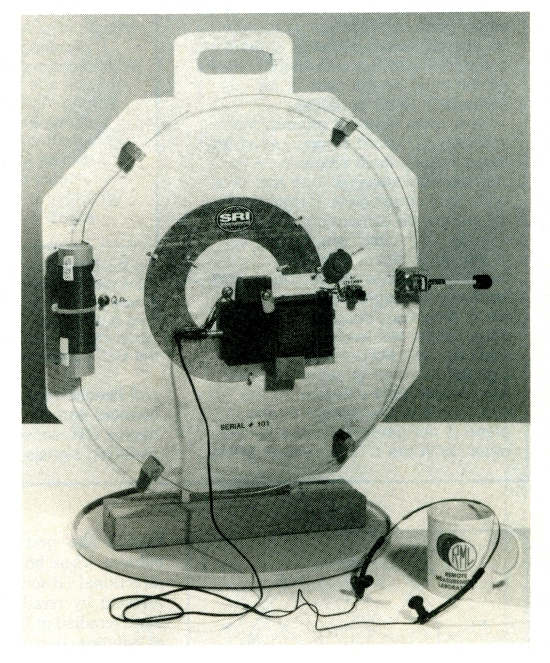
The CTL apparently achieves its cardioid pattern by combining an interior low-impedance loop antenna with an exterior and coplanar high-impedance loop, with the outer high-Z loop supposedly acting like a "bent whip" antenna that generates a so-called "magnetic shadow" region. It seems to be a rather unique antenna, and its detailed mechanism of operation (involving phase shifts, a variable damping resistor, a magnetic shadow region, and two concentric resonant loops) is intriguingly complex and subtle. A good introductory article can be seen here: https://web.archive.org/web/20201218104 ... planar.pdf .
Another detailed article can be seen at the links below (8 pages, as separate links).
http://web.archive.org/web/201912070924 ... ml/bg1.png
http://web.archive.org/web/201912070925 ... ml/bg2.png
http://web.archive.org/web/201912070926 ... ml/bg3.png
http://web.archive.org/web/201912071101 ... ml/bg4.png
http://web.archive.org/web/201912071149 ... ml/bg5.png
http://web.archive.org/web/201912071150 ... ml/bg6.png
http://web.archive.org/web/201912071150 ... ml/bg7.png
http://web.archive.org/web/201912071151 ... ml/bg8.png
The above article states that the magnetic shadow operation of the CTL was computationally and experimentally verified on 78-83 of a 162-page report by Dr. Villard, the bibliographic information of which is here: https://ntrl.ntis.gov/NTRL/dashboard/se ... 8180.xhtml
One experimenter who built this antenna reported on it here, but unfortunately without carefully testing its unidirectional properties: https://sv2yc.wordpress.com/2013/04/27/ ... -w6qyt-sk/ .
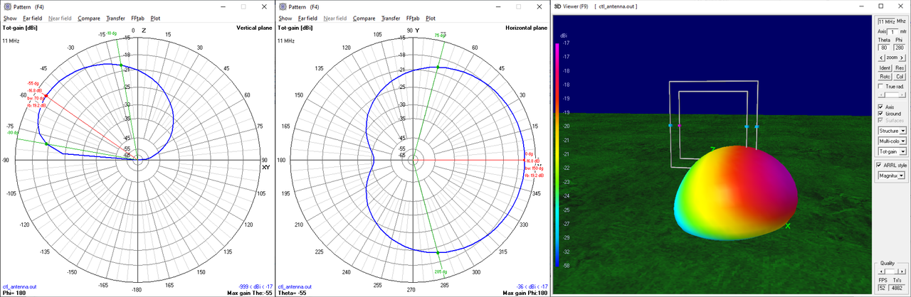
I was hoping that with all of the knowledgeable and interested people here on the forum, perhaps the above links about the CTL might encourage some discussion and analysis of this interesting and mostly-forgotten antenna. Some years ago, I did a preliminary 4nec2 analysis to confirm the unidirectional pattern. I'm not sure if my analysis is meaningful, but it may serve as a starting point for further analysis.
- ctl-pattern-11MHz.png (165.09 KiB) Viewed 30375 times
The 4nec2 file for the antenna simulation is shown below.
Code: Select all
CM Model of Coplanar Twin Loop antenna.
CM Created by qrp-gaijin@yahoo.com (http://qrp-gaijin.blogspot.com).
CM
CM Adjust model as follows:
CM
CM 1. Adjust C2 (outer loop capacitance) to be very large (e.g. 1000 pF), so that the outer loop is far away from resonance.
CM 2. Use 4nec2 optimizer to adjust C1 (inner loop capacitance) to resonate the inner loop (X=0 is the optimizer criterion).
CM 3. Use 4nec2 optimizer to adjust C2 (inner loop capacitance) for maximum F/B ratio.
CM 4. Use 4nec2 optimizer to adjust RL (loading resistance of outer loop) for maximum F/B ratio.
CM 5. Repeat step 3 and 4 until no further improvement is possible.
CM
CM When properly adjusted, the model shows a unidirectional null, both in free space, and above ground.
CM
CM Note that the outer loop must be high impedance (achieved by a loading inductance), and the inner loop must be low impdeance.
CM
CM The outer loop's high impedance allows it to respond to both E and H fields of the incoming wave, allowing for the unidirectional response.
CM
CM The model has initially been adjusted for a unidirectional null at 11 MHz in free space.
CE
SY h=1.0
SY r=6.508e-4
SY c1=3.79e-11
SY c2=6.02e-12
SY rl=70.89846
GW	1	7	-0.5	0	h	0.5	0	h	r	'Wire 1, 9 segments, halve wavelength long.
GW	2	7	0.5	0	h	0.5	0	h+1	r
GW	3	7	0.5	0	h+1	-0.5	0	h+1	r
GW	4	7	-0.5	0	h+1	-0.5	0	h	r
GW	10	9	-0.642857	0	h-0.142857	0.642857	0	h-0.142857	r
GW	11	9	0.642857	0	h-0.142857	0.642857	0	h+1.142857	r
GW	12	9	0.642857	0	h+1.142857	-0.642857	0	h+1.142857	r
GW	13	9	-0.642857	0	h+1.142857	-0.642857	0	h-0.142857	r
GE	0
LD	0	2	4	4	0	0	c1
LD	0	11	5	5	0	0	c2
LD	0	13	5	5	rl	10e-6	0
LD	5	0	0	0	9.9E+99
GN	-1
EK
EX	6	4	4	0	1	0	0	'Voltage source (1+j0) at wire 1 segment 5.
FR	0	0	0	0	11	0
EN