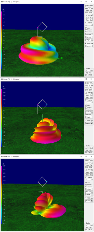
Ok, had the time to run further NEC simulations, and the way the coax is routed does indeed influence the loop pattern,
here's an example

as you can see, routing the coax along the horizontal arm and then down the vertical support or routing it "outside" the loop, makes quite a difference, in the first case, the cardioid pattern is "deformed" so, while there's still backside attenuation, it's lower, plus the upper angle of the beam is vertical, so making the loop sensitive to NVIS signals, changing the setup and routing the coax "outside" the loop, instead, shows a well formed cardioid pattern with a deep null and an upper vertical angle around 20° from vertical, so allowing to better attenuate NVIS signals
Now, I understand that routing the coax that way would be a mechanical challenge, but I think that using a run of thinner coax hanging from the feedpoint at the loop corner, down to a point of the vertical support below the loop bottom corner and then using fatter coax from there to the receiver may be a viable solution; also notice that routing the coax this way will minimize parasitic currents on the coax so, willing to add some chokes, we'd just need them on the "fatter" coax going down the vertical support
As a note, even if the above pic shows the simulation on 40m, I ran the model at different frequencies and ALL of them showed a consistent cardioid pattern with a deep backside null and a lower vertical angle, so I think that the somewhat strange receiving behavior you observed may have been due to the coax interfering (and modifying) the loop pattern
If you want to try running the simulation yourself, here's the model
Code: Select all
CM File: DirLoop.nec
CM Small Receiving Loop antenna
CM with unidirectional pattern
CE

' symbols definition
SY freq=7.100               ' test frequenct
SY hght=3                   ' height of base corner from ground
SY side=0.762               ' length of one side
SY diag=(sqr(2)*(side/2))   ' half diagonal
SY wire=0.00125             ' wire radius
SY vres=530                 ' loading resistor value
SY segm=13                  ' number of segment in wires
SY segs=5                   ' short wires segments
SY wfed=1                   ' feedpoint wire
SY sfed=segm                ' feedpoint segment
SY wres=4                   ' wire hosting the resistor
SY sres=1                   ' segment hosting the resistor
SY spac=(wire*4)            ' spacing to simulate coax

' wires geometry
'  ID seg    x0     y0   z0         x1     y1     z1          wire rad
GW  1 segm     0     0  hght      -diag     0   hght+diag       wire
GW  2 segm     0     0  hght       diag     0   hght+diag       wire
GW  3 segm -diag     0  hght+diag     0     0   hght+(diag*2)   wire
GW  4 segm  diag     0  hght+diag     0     0   hght+(diag*2)   wire

' coax feeder
'GW 10 segs -diag  spac  hght+diag     0  spac   hght+diag       wire*2
'GW 11 segm     0  spac  hght+diag     0  spac      wire*4       wire*2
GW  20 segs -diag  spac  hght+diag -diag  spac   hght-diag       wire*2
GW  21 segs -diag  spac  hght-diag     0  spac   hght-diag       wire*2
GW  22 segs     0  spac  hght-diag     0  spac      wire*4       wire*2

' ground parameters
GE  1
GN  2  0  0  0  13  0.005

' wires loading
LD  5  0  0  0  58000000
LD  1 wres  sres sres vres 0

' enable extended kernel for calc
EK

' feedpoint
EX  0  wfed sfed 0 1 0 0

' initial test frequency
FR  0  1  0  0  freq  0

' end
EN
as it is, the coax is routed "outside" the loop, willing to try the "inside" routing, just uncomment wires (GW tags) #10 and #11 and comment out #20, #21 and #22; what else... oh, yes, with that "outside" coax routing the loop remains directional even up at 90MHz and while the horizontal lobe is wider, the backside "null", even if not as marked as down on HF, is still there, so interference from FM stations will be attenuated and this, in turn, will help receivers with a poor front-end filter
Let me know if you'll need further infos or details
[edit]
forgot, look at the F/B figure of the loop when the coax is routed outside, the NEC simulation predicts 29.6dB of F/B ratio on 40m (38.2dB on 80m and 21.9 on 20m), which means that it could be possible to "cancel" even some blowtorch station just by turning the null toward it !